audiobomber
3 Followers


Recent Profile Visitors


Bookmarks
-
SMPS grounding
SMPS and groundingOver the last month I have been performing extensive tests on leakage currents coming from SMPS power supplies. One of the most important results from this investigations is the makeup of this leakage current.
Previously my understanding was that leakage current was mainly a low frequency phenoninum, 60Hz, and its harmonics (60, 120, 180, 240 etc). My early investigations seemed to show that this was true with some high frequency components from the switching operation, but that this was fairly small in comparison to the whole. This turned out to be not true. It turns out that SMPS leakage is very hard to measure, it consists of some VERY high impedance components, on the order of 300 Mega ohms and some much lower impedance components.
None of the standard electronics test equipment will properly measure this, there impedance is simply too low and drastically changes the signal while trying to measure it. My only option was to build my own ultra high impedance differential probe (around 10 Giga ohms) so I can measure leakage current directly (rather than its affect on other equipment).
Because of this ultra high impedance it turns out leakage current can go all kinds of places you don't think about. It turns out to be extremely difficult to block using normal techniques, the blocking device has to have over a giga ohm to significantly attenuate it, this is VERY tough to achieve.
It turns out the best way to deal with this high impedance part is to shunt it around the audio equipment, there is a very easy way to do this, ground the negative output of the SMPS. It seems that even SMPS that include a ground pin don't actually use it for anything. This sounds too simple, but it actually works. PLEASE do not under any circumstances attempt to modify an SMPS to do this, this is DEADLY, DO NOT attempt!!!
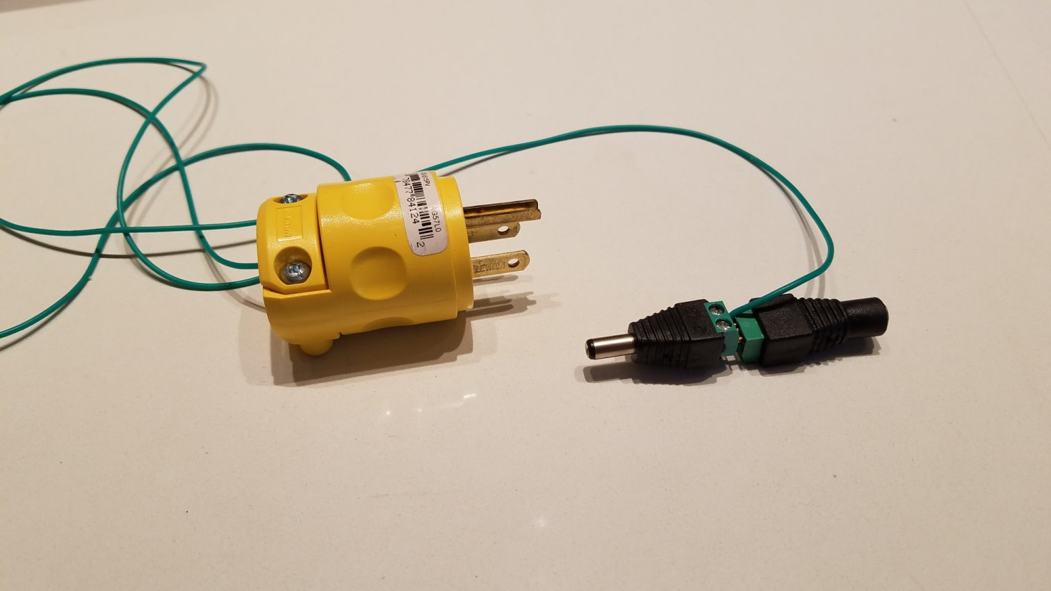
Fortunately there is a real easy - inexpensive way to do this, it doesn't take any complex knowledge, I'm calling this the power supply grounding adapter, here are a couple pictures:

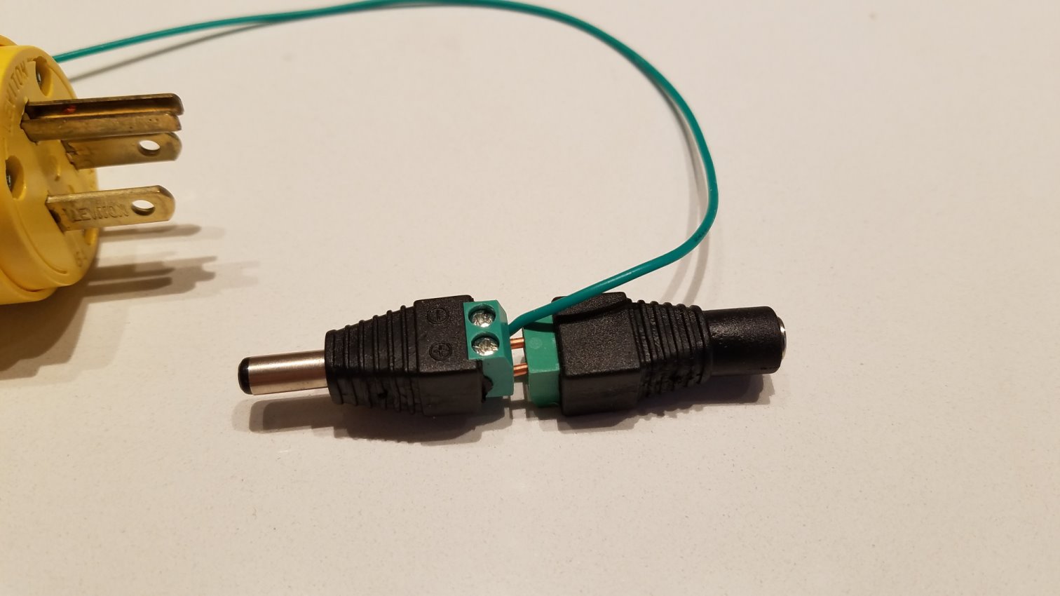
This consists of three items and some wire. The yellow item is a three pin AC power plug (shown is the US model), the black parts are male and female DC barrel connectors with screw connectors, no soldering necessary! Amazon has a whole bunch of places selling these for CCTV cameras. The spec is 5.5mm outside and 2.1mm inside. Most you will see will be this spec. The + of the male is wired to the + of the female and - on the male goes to - of the female. Look at the close up picture, in order for the wire to go straight across one of the connectors has to be upside down. This is extremely important to get right. You can use many different types of wire for this, I used solid core 14AWG wire with the insulation stripped off.
A green wire goes from the ground pin of the AC plug to the - pin of one of the connectors, strip a little off and just stick it in with the wire going between the two connectors, use a screwdriver to tighten the screws, you are done.
The green wire does NOT have to be a heavy duty high power wire. The SMPS are already designed to be double insulated so the AC cannot show up on the DC output, grounding it does not pose any electrical threat. I just used some nice silicon rubber wire I bought on Amazon, but really any green wire will do.
You plug the output of the SMPS into the "jack" side, and the "plug" side goes into where you would have plugged the SMPS. The AC plug goes into the SAME power strip or duplex outlet where you plugged in the SMPS. This is very important to properly shunt the high impedance part of the leakage current. If it goes into a different circuit you can wind up making it worse.
You should do this on every SMPS that is somehow electrically connected into your sound system. Some items may have different connectors such and Ethernet switches etc. There are a bunch of different adapters available that can convert the 5.5/2.1 to just about anything out there, you may need to use a pair of these.
You may ask "how effective IS this?"
Here are some graphs, the first is the leakage current of an SMPS, the second is with this adapter plugged in:
That is a significant reduction in leakage for a $10 shunt adapter.
If you want to get it all you will have to use something like the LPS-1 which will get rid of it all.
Have fun,
John S.
-
15 USB/SPDIF converters shootout
15 USB/SPDIF converters shootoutIf you have the option to skip USB output, if you have a DAC that accepts AES-EBU or I2s or SPDIF or something like that is that a better choice than buying a converter to convert usb to spdif?And if yes, or its way more costeffective to keep the DAC and avoid the USB connection to start with, which kind of device do I use to output from my PC? I have all my files and music stored on my pc, and needs to output to a DAC(which I havent bought yet still wondering what to buy in 1500$ range), should I buy a dedicated soundcard or pci-e card(whichever gives the best output), or just buy any kind of cheap soundcard for 80-100$ and it will do fine? I mean id rather save money on a dedicated soundcard for 500-700$ and/or a usb-spdif converter and spend the money on the DAC and amplifier.
So which solution is the most costeffective?
No one should generalize enough to answer the first question. Whether or not to use a DAC's built in USB input depends entirely on how well that USB input is implemented. The same is true for an SPDIF input as well. For example, if a DAC uses the popular Crystal SPDIF receiver chip, it adds at least 200 pS of jitter right there, even if everything else is "perfect". These are complex questions and cannot be simply answered.
But, technically speaking, if a USB input is implemented correctly with the best engineering, it will outperform a SPDIF input with a similar level of implementation. No matter what, SPDIF is technically the poorer interface design, because four signals (master clock, bit clock, word clock, and data) are converted to one on the send end, and then converted back to four again on the receive end, in a real time (not asynchronous, with the exception of a very few, very expensive DACs) data stream without any error correction.
If one has a DAC where SPDIF has been confirmed to be the best input option, then a really, really good SPDIF source is in order to get the best performance out of that DAC. My suggestions for this case would be either the Berkeley USB-SPDIF converter, or for a an Ethernet streaming solution (which has the potential to outperform the USB converter approach) something like a high end Ethernet to SPDIF device like the Sonore Signature Rendu.
-
RADIO ON MINIMSERVER
Radio lossless streaming (.flac)2 hours ago, znorter_1 said:for lovers of Classical the Czech channel "D-dur" is superlative!
for your knowledge ...
Minimserver/Ministreamer (full license + yearly maintenance to enable MinimStreamer) can play internet radio streaming, flac too.
Just define a folder inside the path analyzed by Minimserver, I defined Radio
Inside the Radio folder define one folder for each radio station.
Each radio station folder must contain a .m3u file and a jpg/png file for the logo
A couple of exemples of .m3u file:
-
Radio Paradise Main Mix.m3u
- #EXTM3U
- #EXTINF:-1,[*;flac] Radio Paradise Main Mix
- http://stream.radioparadise.com/flac
-
D-dur.m3u
- #EXTM3U
- #EXTINF:-1,[*;flac] D-Dur Classical
- http://amp.cesnet.cz:8000/cro3.flac
... and it works!
now playing D-dur (flac) ...
-
Radio Paradise Main Mix.m3u
-
Settings
Best investment to upgrade my digital chain?I found it puzzling at first as well. Don't fret. It works great.
First, go into Eunhasu Music Player (at the IP address set for the SoTM)
Go to Control HQPlayer NAA and click on it to install it on your SoTM
Then if it's not "active" after install (I think it will be) click on it to activate it.
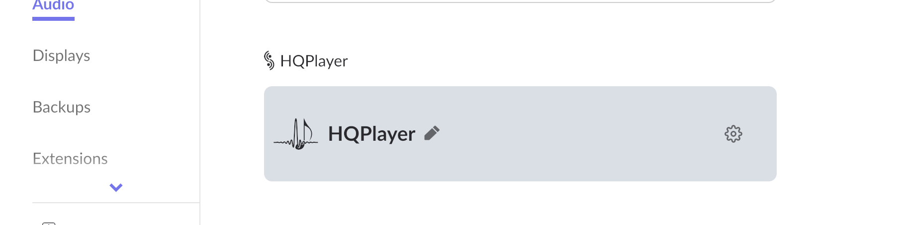
The go to Roon Settings > Setup > Add HQPlayer
Then start HQPlayer on your computer - don't exit it, you can minimize it be leave it running
While HQPlayer is running go to the program title in the top menu bar and choose Preferences
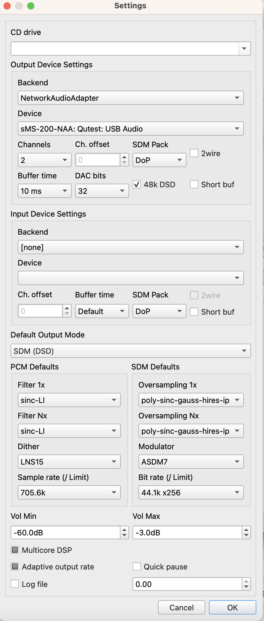
There will be a lot of settings - I've added a photo of mine. You'll see the Backend setting, the device setting, etc. In time you'll learn how to set those.
You close the Preferences settings box after clicking OK. Still keep HQP application running on your computer.
Go To Roon > Settings > Audio > and select HQPlayer as the output. There are some basic settings there, too.
That's it. Let me know if you have more questions. Here's some photos to help:
-
DC cables
DIY DC power cablesThere has been a lot of posts recently in other threads about making your own DC cables for LPS-1, JS-2, Y adapters etc.
I'm going to attempt to give some theory behind DC cables and CA and some hints for making your own, and some results of my own experience.
So what is the big deal, DC is, well, DC! Resistance should be the only thing that matters, right? Wrong! Particularly for power digital circuits some AC issues actually do make a big difference. This is due to the fact that the load current of most digital devices is not constant, it varies all over the place, and can do so very quickly. This rapidly changing load current causes a voltage to develop across the inductance in the cable. No matter how good the regulator in the power supply is this noise will still be there. This means that both resistance and inductance of the cable matter. Cable capacitance is a good thing, but the ranges available in cables have a very small effect so so you can pretty much ignore the cable capacitance.
Are there "cable parameters" that DON'T matter for a DC cable? Yes, anything that primarily affects distortion is not an issue, such as stranding vs solid core, conductor material and plating. The difference in resistance between silver and copper does produce lower resistance than copper, but just making the copper conductor slightly thicker does the same thing. Thus I do not consider the vastly higher price of silver worth it. The net result is that stranding doesn't matter, OCC etc doesn't matter, dialectric has extremely small effect.
So what DOES really matter? The wire gauge determines the resistance and the geometry of the wires (how they are arranged in the cable) makes a HUGE difference in the inductance. So things to optimize for, thick wires and use the proper geometry. The geometry is actually far more important than the wire gauge, although you don't want to go with really thin wires either.
There are 4 common geometries in use in DC cables:
parallel conductors (zip cord)
coax
twisted pair
starquad
They are listed in decreasing inductance, zip cord has about 10 times the inductance as starquad for equivalent gauge. Coax and twisted pair are pretty much the same at about 1/3 the inductance of zip cord.
All can be shielded or not shielded. The shield does not really make things better for most applications of DC cables, but if it is done wrong (which is extremely prevalent) it can make things worse. Thus I recommend using unshielded cable for most situations.
I hope from the above you come to the conclusion that using starquad is a good thing when making your own DIY DC cable.
So what is starquad? It consists of four conductors, the whole group of which is twisted in the cable. This is NOT two twisted pairs. They are not woven or braided, the four conductors are arranged in a square. Diagonally opposite conductors are connected together at both ends of the cable. That is it, not very complicated. There are many articles on the net covering starquad with nice pictures. (sometimes it is called star quad, sometimes star-quad, they are all the same thing)
So what is special about starquad? Well of course you have two wires in parallel which halves the resistance, but the big thing is the magnetic field, it forms in such a way that the inductance is about 3 times lower than coax or twisted pair, AND it produces an inherent very good shielding effect, without using a shield!
So to make your own starquad cable you need a cable with 4 conductors, with the whole thing twisted, preferably unshielded. There are many of these on the market. They do not have to be specifically marketed as starquad. Many cables that say "starquad" have wires with only two colors, diagonally opposite wires have the same color, that makes it easier to figure out which ones to connect together. But cables with different colors for all for wires also work well, you just have to figure out which ones are diagonally opposite each other.
So what gauge to use? A 24 gauge starquad microphone cable is probably too small, and a 14 gauge speaker cable is probably going to have wires that are impossible to connect to the barrel connectors most components use. So somewhere in between is probably a good choice, 20 or 18 AWG wires are probably the sweet spot. Belden 8489 and West Penn 244 are 18AWG 4 conductor unshielded cables that work very well. Canare makes a starquad speaker cable called 4S6 which has 20AWG wires which should be a very good choice as well.
Alex likes to use a cable with a shield which I think just makes things more complicated than they need to be.
If you want to make your cable without soldering anything there are barrel plugs with screw terminals available at many places. These terminals will accept a single 18AWG wire nicely, but it gets very tricky to put two 18AWG wires into each connector (which is what you have to do for starquad). The 20AWG 4S6 might be a better choice when using these. If you want to make a Y cable where you put TWO cables into one plug, you may just barely be able to get 4 20AWG wires into each connector.
Last night was the first time I was actually able to try some of this myself. Since I am on the road now without my soldering equipment I decided to try a starquad cable with the screw terminals. My entire setup right now is an LPS-1 powering a SqueezeBox Touch (SBT) with Senheiser phones plug in to the SBT. The current setup used a simple DIY 16 AWG zip cord cable with soldered on barrel plugs. So I found a small amount of 244 on ebay and a bunch of screw terminal connectors on Amazon. They were all here yesterday.
Then started the fun, the two 18AWG wires do NOT fit well in those screw terminals. Every time I pushed them in a strand or two would not go in and curl off to the side shorting out to the other terminal. I had to try it about seven times to get all 4 wires properly inserted into the plug. The wires are pretty stiff so I had to really tighten those screws down tight to keep them from pulling out. It only took five tries on the other end of the wire.
I finally got it together and plugged it in, WOW this was a big improvement! I thought this system sounded amazing, but with this DC cable it was dramatically improved. And that less than 10 dollars!
Next I'm going to try the 20AWG 4S6 cable and see how that sounds.
John S.
-
EMI/RFI
RFI/EMI Is the EnemyHere's the go for EMI/RFI on how it affects audio systems.
For Frequencies at 30MHz and lower, EMI is limited to conducted systems, that means through wires, silver, silver plated, gold, copper, o2 free copper, all of them.
Conducted noise is usually common mode noise, a filter, of resistance (R), inductance (L), capacitance (C) combo, removes (in a very high level sense). The change in the RLC like a signal, power, DC supply cable affects the reduction. More dramatic reduction is direct application of an EMC filter, (better) dual filter in the AC network or in Ethernet systems.. SMPS noise is conducted noise.
For Frequencies above 30MHz, radiated noise is the problem, such as a radio transmission so strong it can interfere with electrical circuits.
Mitigation is by way of shielding structures, earthing those structures, in case of PCBs, extremely careful layout and lots of ground planes, especially for wireless!
Knowing the source and applying the right technique can reduce the impact of unwanted noise in audio systems.
Benefits I've found over the years to reduce common mode noise:
- Wider, higher, deeper Soundstage
- Readily distinguish very small audio (like a triangle)
- Treble is less 'splashy'
- Increased bass and definition
-
The EtherREGEN thread for various network, cable, power experiences and experiments
The EtherREGEN thread for various network, cable, power experiences and experimentsI have covered this topic exhaustively in many posts and some papers on the UpTone website. Digital audio networks seem to be "disturbed" by two different things, jitter on the data and common mode current on the wires. These are actually converted one to the other in many places in the network path. The end result of this is jitter on the clock and data in the DAC subtly changing the analog signal output from the DAC.
This has absolutely NOTHING, I repeat NOTHING to do with the data bits being corrupted, check sums etc. It has to do with subtle changes in timing of the data bits and small ground plane differences getting into the DAC through the normal network connections. The Data doesn't get corrupted in any way, the bits are still the same.
There are some big misconceptions about optical network connections. The optical connections do NOT make the timing perfect. They do NOT "reclock" the data. whatever jitter that is on the input is still there on the output, in fact the electrical to optical and back to electrical ADDS jitter to the signal. All higher quality optical equipment can do is add less jitter to what is already there, it CANNOT reduce it. What is beneficial is that it completely blocks the common mode noise including leakage currents from power supplies. It blocks one of the issues but makes the other slightly worse. All higher quality optical equipment can do is make that "slightly less" even less, but it is still there.
I have a huge amount of detail on the processes involved if you really want to get down into the details.
John S.
.png.3af65e0abe1f4421ccde11e5369dd87f.png)